|
As received, my lathe only came with a single set of gears to drive the leadscrew.
According to the chart on the lathe, the supplied gears would allow either 0.5mm / revolution of the chuck
for threading, or 0.05mm / revolution for power feed.
As I wanted the ability to cut screw threads other than M3, this was a serious limitation.
A fruitless search of the Internet for change gears to suit my machine proved I would have more success
buying hens teeth, or require Donald Trumps bank account.
After much research I came to realise that cutting gears is not actually all that difficult, once you have the right equipment.
Equipment
The equipment I used consisted of the following major items:
1/ Lathe for turning gear blanks to size and boring center hole.
2/ Mill for cutting gear teeth (gaps really).
3/ Vertically mounted rotary table on mill with indexing plates.
4/ Homemade arbor to mount gear blank in lathe and transferring to rotary table on mill.
5/ Set of Module 1 involute gear cutters.
Module 1 Gears
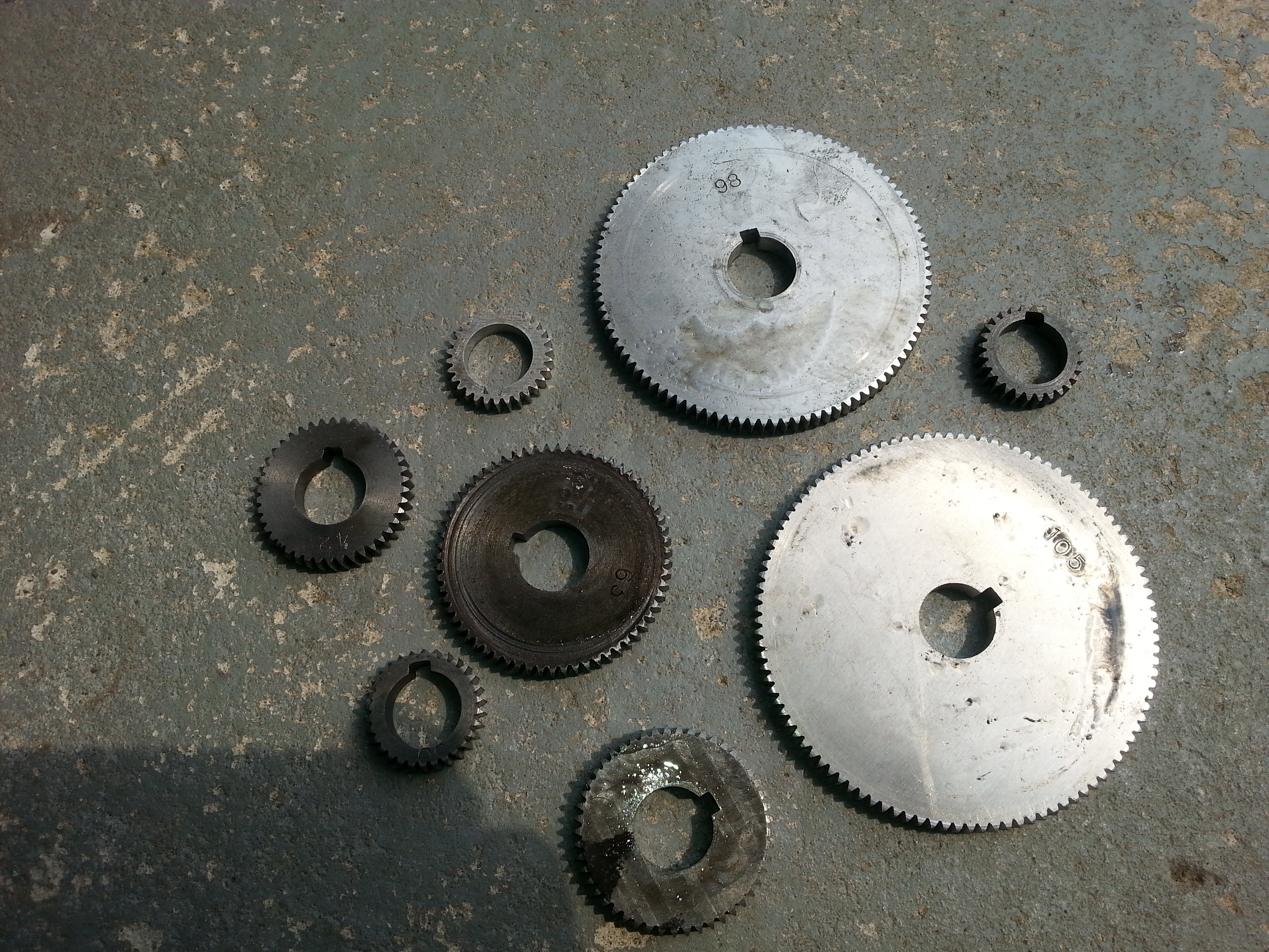
I determined the lathe most likely used Module 1 gears by measuring the outside diameter, and counting the
number of teeth on the available gears.
My 70 tooth gear measured 72mm in diameter, which agreed nicely with the information I found on this website
http://www.metrication.com/engineering/gears.html.
Likewise, my 84 tooth gear measured 86mm in diameter.
Module 1 it was.
I subsequently purchased a set of Module 1 gears from ZFE STORES on ebay for 127 AUD.

Rotary Table
Ever since I purchased my mill I desired a rotary table.
Initially the thought was for cutting arced slots or outer sectors, but the other useful function is as
a dividing head, especially useful for gear cutting.
The need to cut gears cemented the decision and when Hare and Forbes presented a nice 6 table
with indexing plates for 400AUD during their usual November sale, SOLD.
As a bonus, this kit provided me with a 5 3 jaw chuck for the lathe. Win win :-).
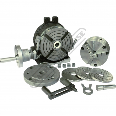
When cutting gears, I utilise the #2 Morse taper in the center of the table.
Gear Blank Arbor
To maintain concentricity, I decided to machine an arbor to mount the gear blank upon after being
bored to the correct size to fit the change gear shafts.
On my lathe, this was a 20mm hole, with a 5mm key way.
The arbor required a #2 Morse taper to fit in the rotary table.
To fit into the #3 Morse taper of the lathes headstock, a 2-3 Morse taper sleeve was utilised.
Fortunately my lathes compound could just provide enough travel to cut the length of a #2 Morse taper.
To set the taper, a commercial shank (eg jacobs chuck adapter) with a #2 taper was mounted between centers,
then a dial indicator was used to prove zero runout as the compound was wound along the length of the taper.
IMPORTANT - it is essential the indicator is adjusted to measure at the true center height of the lathe.
Referring to the table of gears on the lathe, the smallest gear needed to be 28 teeth, ala 30mm in diameter.
As the depth of each tooth for Module 1 is around 2.4mm, this meant the largest diameter on the arbor adjacent
to where the gear blank is mounted would be 5mm less than this, ie: 25mm.
30mm bar stock was thus chosen to build the arbor from.
Another important design criteria is ensuring enough space exists between the gear blank and the surface of the
rotary table when mounted for gear cutting. If not, the gear cutter will collide and mar the surface of the rotary table.
Poor form.
Machining starts by center drilling each end of the 30mm stock.
The 30mm stock is then mounted between centers on the lathe and roughed out for the mounting hub and taper areas.
The #2 Morse taper is then cut using the compound.
IMPORTANT - it is also essential that the tools height is adjusted to be at the true center height of the lathe,
matching the dial indicator position used earlier.
I found I needed to remove the compounds handwheel as it fouled the tailstock when winding across the
length of the taper.
An extension shaft was fitted in place of the handwheel, which then allowed winding of the compounds
leadscrew to take place beyond the tailstock.
This also allowed power feed by chucking it in a cordless drill. There is an additional benefit doing this, I found
a slight wander in the gibs when hand winding due to the leverage of the crank position.
Once the Morse taper is cut it is tested by using a suitable #2 Morse taper socket.
The 2-3 sleeve was perfect for this.
Tweaking of the taper is likely to be needed.
The work is then transferred to a chuck so the end of the taper can be drilled and tapped to M10.
This allows the taper to be secured in the rotary table by a drawbolt, otherwise loosening due to
vibration is highly likely when cutting the gears, which would be disastrous.
Once this is complete, the work is reversed, and the sleeve used to mount the work in the headstock using the
freshly machined Morse 2 taper. To ensure the sleeve can be later removed, it may be advisable to insert a
M10 grub screw in the end to allow a drift to reach and separate the arbor from the sleeve.
As my sleeve has a tang, it was not possible to use a drawbar to secure the work in the headstock of the lathe.
Instead the tailstock was used with a live center to prevent the work from advancing forward out of the headstock.
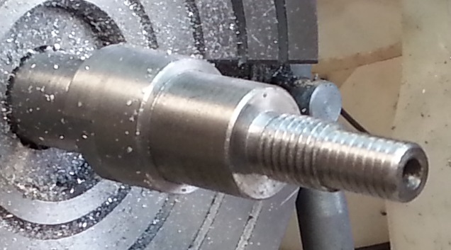
The remainder of the arbor is now turned down to final sizes.
Most important here being the diameter of the arbor where the gear blank mounts.
Measure the change gear shaft with a micrometer, then use the same micrometer to check the work.
The gear blank is secured with a screw on collar.
I would have preferred this to be M16 or so, but a chicken or egg situation was evident - I couldnt single point the
thread as I dont have change gears!
Instead I settled for the largest die I had to hand, M12.
Note: ensure the threaded section is long enough to take the collar, and a lock nut behind.
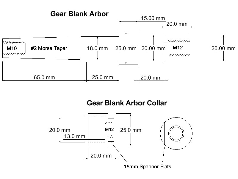
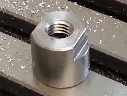
Once complete, work can commence on the screw on collar.
The outer diameter should match the step on the arbor (25mm). The inner should be bored
to a depth suitable to clamp the gear blank and neatly fit over the remainder of the precise
20mm shank on the arbor.
As my gears were 8mm thick and the mounting diameter was 20mm long, I made the depth
of this bore 13mm, which allows 1mm free space.
The remainder is drilled and tapped to M12.
Flats were cut to allow an 18mm spanner to secure the blank by tightening the collar, followed
up with a M12 lock nut.
Finally to ensure the gear blank cannot rotate on the arbor, a key slot was cut in the arbor to
5mm width, matching the key cut into the gear blank.
A short length of key steel is then used to register the part.
Gear Blanks
Various materials were tried for the gears.
Despite the mess, I do like the results when using cast iron, which I cut from an old disk brake rotor.
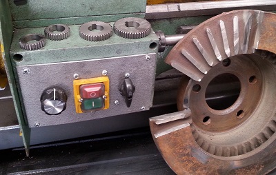
However, this would not provide large enough blanks for the larger gears.
I sourced some discarded BBQ plates from the local tip shop, but this proved to be folly.
Those BBQ plates were so damn hard they readily destroyed abrasive cutting disks and,
even worse, gear cutters.
I eventually sourced some 8mm plate aluminium in 5083 grade and used that for the larger gears.
I found it machined nicely.
The actual creation of the gear blank follows the same process irrespective of what sort of material you use.
First step is to cut the blank to rough size larger than the end diameter.
This is then mounted in a chuck so the hub can be bored to size.
I drilled to largest size I had available, 0.5, then used a 16mm end mill.
Following that the hole was progressively bored out to 20.00mm, checking with a bore gauge and micrometer.
A 5mm key way was then broached using a piece of 5mm HSS ground like a parting tool, mounted horizontally
in the toolpost, centered at the center height. Gentle advances with the cross slide and plunging into the work with
the carriage soon creates a nice key slot.
I did file the key way into the first gears, but broaching leaves a much more accurate result.
The gear blank is then mounted on the arbor, fitted up with a 2-3 sleeve and installed on the lathe.
The tailstock is used to prevent the arbor vibrating loose from the headstock.
The work is then turned to the correct outer diameter for the gear being cut.
In this case using Module 1 gears, the diameter calculation is dead easy, just add 2 to the number of teeth required.
eg a 49 tooth gear would be 51mm diameter.
The work can now be transferred to the mill for cutting the gear teeth (or gaps if you prefer).
Cutting the gear
Setting the division plate
Before cutting the gear, we need to consult the manual for the dividing head or rotary table to determine the
correct number of turns of the handwheel to advance the correct angle for each cut.
As a word of caution, I found the manual supplied with my rotary table to be a book of lies.
It told me to use division plates that were not even part of the equipment supplied. (I had 3 plates, the book only had 2).
I had to resort to calculations to ensure I was using the correct division plate and number of holes.
For my very first gear, I chickened out of the division plates and tried a 30 tooth gear.
This works out to be 12 degrees per tooth (360/30), or exactly 3 turns of the handwheel on my 90:1 rotary table
(4 degrees / turn).
All other gears are likely to require use of the division plates and sector arms.
Once you understand the process, you will find the use of whole numbers and fractions is clever and elegant.
- Select the correct division plate with the required circle of holes.
- By counting holes in the correct circle, set the sector arms for the fractional remainder.
- Install the locating pin cum winder so it aligns with the correct circle of holes.
- Advancing the table for each tooth simply requires turning the correct number of full turns plus any
remainder (holes), guided by the sector arms.
- Always advance in the same direction.
If you overshoot wind back a full turn then approach again in the correct direction.
This eliminates backlash in the rotary tables gearing.
- Lock the table for each cut made.
Setting the gear cutter
Involute gear cutters cut the gaps for a particular range of teeth. Gears with less teeth require a wider gap
near the circumference to admit the mating tooth as the gear rotates.
You must therefore firstly select the correct gear cutter from the set of 8 for the number of teeth you wish to cut.
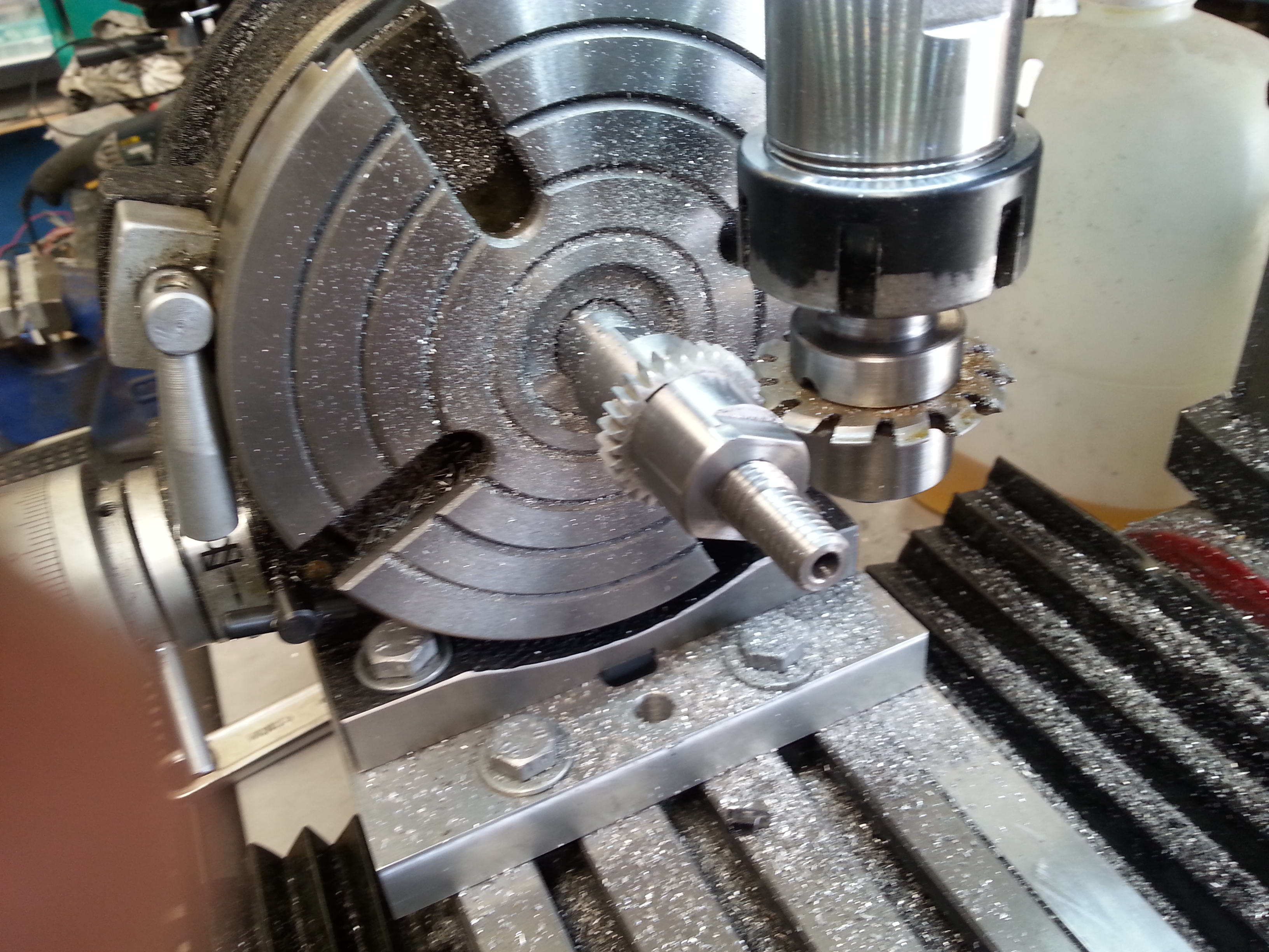
Once the correct cutter is selected, it must be mounted so the cutting edge is directly in line with the center of the gear.
This of course translates to the center of the rotary table:
- Mount the gear cutter on a suitable mandrel in the mill.
- Use a center in the rotary table
- Adjust the Z axis of the mill to align the tip of the cutter with the point of the center.
- Lock the Z axis in place.
Next step is to determine the correct depth of cut:
- Replace the center in the rotary table with the arbor holding the gear blank.
- Secure the arbor with a draw bolt so vibration will not loosen the morse taper.
- Set the Y axis so the gear cutter is clear of the work.
For safety, the gear cutter should be away from the operator, with the work in front.
This keeps the gear cutter well clear of fleshy human bits when advancing the rotary table.
- Move the X axis so the gear cutter is now in line with the work.
- Carefully bring the Y axis in so it just touches the work. STOP.
If you have a DRO, zero the Y at this point.
- Move the X axis so the cutter is away from the rotary table.
- Wind in the Y axis the required depth of cut. I used 2.4mm.
The gear gaps are cut to full depth in one pass, using conventional cutting.
- Lock the Y axis.
You are now ready to cut teeth.
Once started, try to avoid distractions as it is quite easy to lose track of turns on the rotary table.
- Advance the rotary table to take up any gear train backlash.
- Lock the rotary table.
- Wind the X axis in and take the first cut.
- Wind the X axis back out.
- Unlock the rotary table.
- Advance the table the required number of turns & holes.
- Stop and check the gear cutter appears to be correctly aligned for the next cut. If not check the advance.
- Repeat from step 2 until all gear teeth are cut.
- With all things going right, the gear cutter should finally be once again aligned with the initial cut.
Congratulations, you have just finished a shiny new gear!
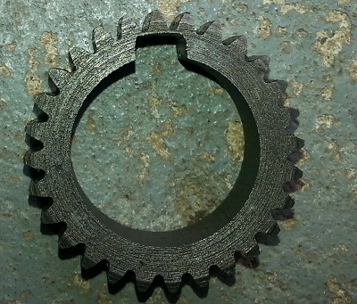
A cautionary tale
You may recall earlier I mentioned a 28 tooth gear.
I dont know what drugs the manufacturer of this lathe was on, but this gear is not going to be usable.
The depth of cut of the teeth, in conjunction with the key way leaves virtually no metal at the key way
and therefore an extremely weak gear. I can see this gear lasting a few revolutions at most.
|