|
|
|
This page presents information on a DCC Locomotive Decoder |
|
|
||||||||||||
|
See it in action The following video was shortly after the very first upload of code to the target PCB. |
|
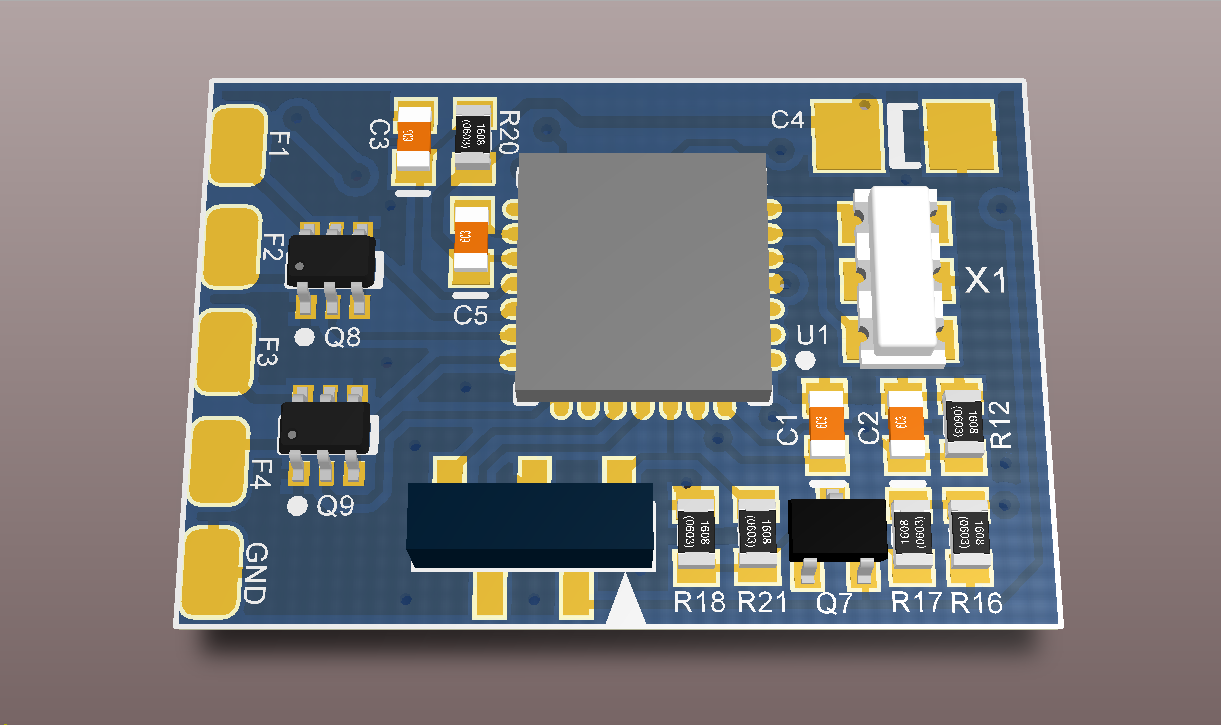
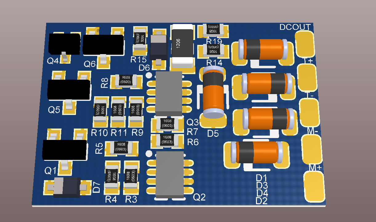
Design Genesis The original concept began from a Loco Decoder design that can be found on the Model Electronics Railway Group: The original design was by Mike Bolton and the software written in PIC assembler by Gil Fuchs, both members of MERG at the time. Using the schematic for the Merg V13 decoder I designed a double sided surface mount PCB. Despite being a faithful copy of the V13 schematic I was unable to get the decoder to reliably function. I decided I needed to shrink the PCB, and also understand the inner workings of the code. The final PCB measures 21mm x 14mm, using a 28 pin QFN package for the PIC. |
|||||
|
Design Files Schematics, PCB designs and software for the loco decoder can be found on this page |
|||||
|
Planned updates This page details current known issues, and future directions |
|||||
| This page has been accessed
|
|||||
| [Home] [Hobbies] [Model Railways] [Electronics] [Hobby Machining] [Favorites] [Photo Gallery] [Stats] |

