|
|
|
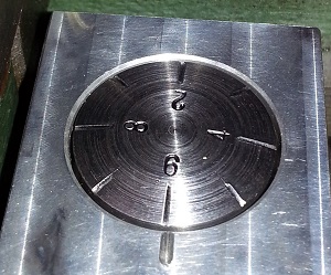
On this page I present a thread dial indicator I built for my lathe when cutting metric screw threads.
A thread dial indicator tracks revolutions of the leadscrew when screw cutting. It is essential that the drop in point used to engage the half nuts is consistent from pass to pass. This is important to ensure the tool follows the same path across the workpiece otherwise double start threads may result. My lathe has a 3mm leadscrew, driven by sets of change gears in the gearbox area to the left of the headstock. By selecting suitable change gears, the saddle will advance towards the headstock by a known distance per revolution of the chuck when the half nut (theres only one half on this machine!) is engaged. As metric threads are specified as a pitch, and not generally fractions of a known distance several sized gears are actually required to keep track of the leadscrews rotation and allowable drop in points. The general formula for defining drop in points is: Leadscrew Pitch * Number of Indicator gear teeth The result of this calculation must reveal a whole even number for a valid drop in point. As I inscribed 8 lines into my indicators surface dial, the number of divisions that can be reliably used in the above equation is 8, 4, 2, or 1.
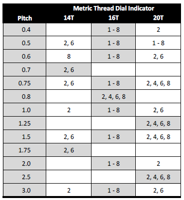
8 means any line, The other unknown is the number of gear teeth to use in the indicator. For example, if I wish to cut a 1mm pitch screw, using the above equation I can determine the following usable drop in points: 14 teeth: (3 * 14) / (1 * 8) = 5.25 16 teeth: (3 * 16) / (1 * 8) = 6 OK 20 teeth: (3 * 20) / (1 * 8) = 7.5 It is clear that I could use any of the available gears on the indicator, BUT using the 16 tooth gear provides the fastest repetition point of only 2 revolutions (16 / 8) of the leadscrew vs 14 (14 / 1) and 10 (20 / 2) for the 14 and 20 tooth options respectively. One of the most troublesome pitches is the 0.7mm pitch. 14 teeth: (3 * 14) / (0.7 * 8) = 7.5 16 teeth: (3 * 16) / (0.7 * 8) = 8.5714 20 teeth: (3 * 20) / (0.7 * 8) = 10.7143 The only usable drop point uses the 14 tooth gear, and then only using either number 2 or 6 on the dial. Thus the repetition point is 7 (14 / 2) revolutions of the leadscrew. Below is a table of drop in points I determined to suit the thread dial indicator I built.
The next page details the construction of my thread dial indicator. |

| [Home] [Hobbies] [Model Railways] [Electronics] [Hobby Machining] [Favorites] [Photo Gallery] [Stats] |