|
|
|
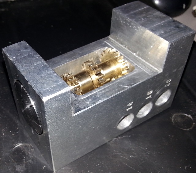
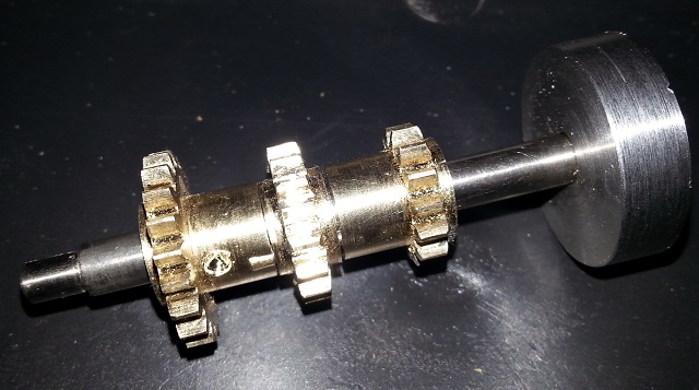
Continues from Thread Dial Indicator. To get a visual idea of the finished unit, heres a photo of the fully assembled unit:
As can be seen, there are 3 separate gears (14, 16 and 20 teeth), which are brought into A lock screw then clamps the indicator to the stud once correctly installed.
The gear to be used is determined by which thread pitch is desired using the table on the previous page.
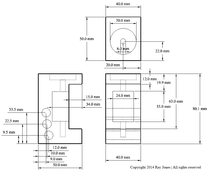
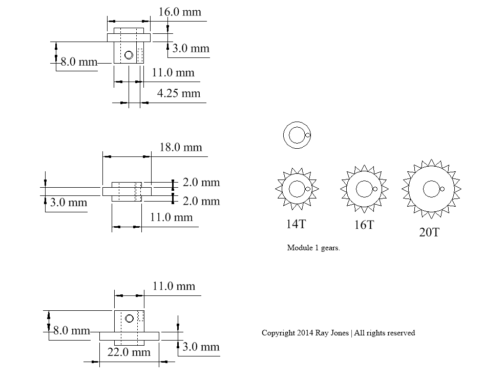
Construction Drawings
The body is milled from 40mm aluminium stock. A pocket is required to house the gears. A longitudinal 6mm hole is drilled to accept the shaft that holds the gears and top indicator dial. 3 cross holes are drilled to fit the unit upon the saddle and mesh the appropriate gear. A 30mm wide, 7mm deep pocket is bored upon the top surface to house the indicator dial.
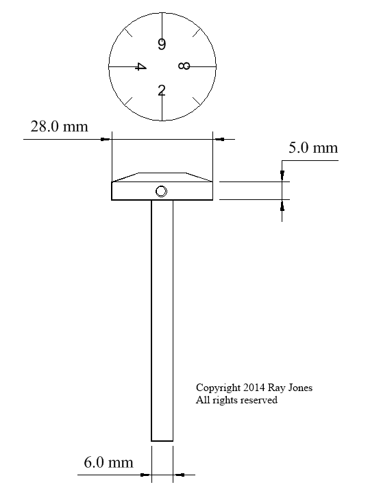
The 6mm shaft was sourced from an old dismantled printer as it had a nice polished finished. The indicator dial should be cross drilled and tapped to M3 in line with the 2 indicator.
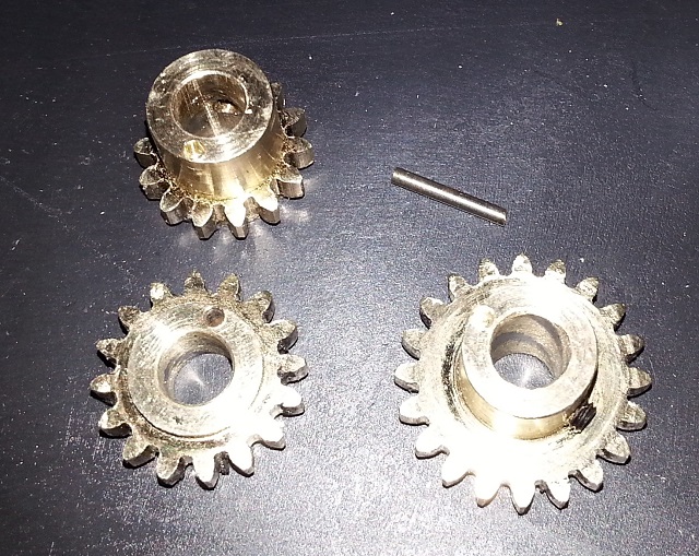
The gears were machined from brass, using a module 1 gear cutter. The 14 and 20 tooth gears each have a large hub within which a grub screw is fitted. As the 16 tooth gear is too thin, it is pinned to each neighbouring gear. The diagram below in the plan view shows the pinning holes in each gear.
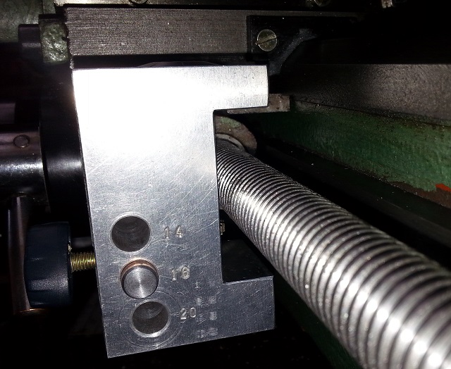
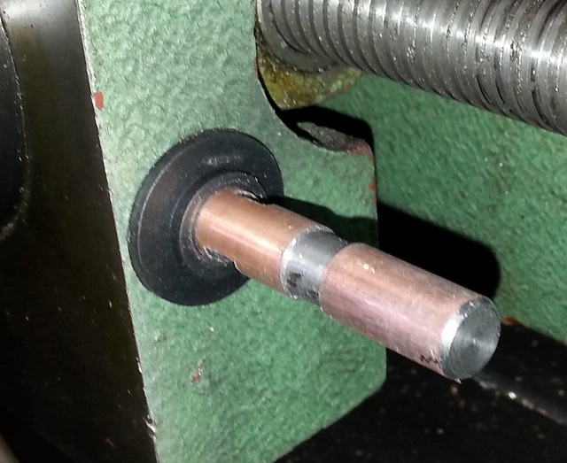
Once fully assembled, the unit was offered up to the side of the saddle meshing one of the gears with the leadscrew. A transfer punch was used to mark the side of the saddle, and an M6 hole was drilled and tapped. A 10mm shaft was prepared with a short 6mm thread at one end and a central relief to prevent the locking knob
Finally the spacing from the side of the saddle needs to be determined so the gauge can be readily Recall that the tips of all the gear teeth align with the 2 position on the indicator. Once this location is determined, the space between the saddle and unit is measured using bits of stock, feeler gauges etc. To test the final installation, engage the 16 tooth gear and try and drop in upon any line. If this succeeds, then try the 14 tooth gear. Finally test the 20 tooth gear. A PDF file of my original turbocad drawing is available. This should provide clearer rendering than some of the images above. Final Thoughts As the BV-20 latch does not have a slotted power feed shaft, the dial indicator will also be very useful when used in the 16 tooth position. If you have any queries with the construction, please feel free to drop me line at web@mrjones.id.au
|

| [Home] [Hobbies] [Model Railways] [Electronics] [Hobby Machining] [Favorites] [Photo Gallery] [Stats] |